A large number of equipment such as cnc machine tools and machining centers are used in mold manufacturing. The manufacturing cycle is long. Operators are prone to fatigue. Once a failure occurs, it often takes a few seconds from human perception to take corresponding measures, which may lead to product scrap , Causing serious economic losses. There are many domestic and foreign research reports on tool breakage and machining fault diagnosis in general parts processing. Most of them are concentrated on acoustic emission, cutting force or vibration monitoring, etc., and great progress has been made. However, the processing is complicated. Molds and other workpieces with free-form surface characteristics still lack effective monitoring technology. The reason is that the over-cut signal is difficult to recognize. Another is to provide effective means for real-time monitoring. This article uses current signal processing tools-wavelet analysis. “Focused” scanning is performed on the different time periods and frequency bands of the original signal to accurately extract the over-cut signal from the time-frequency space. 1 Wavelet analysis concept Wavelet analysis is the development of Fourier analysis. It uses a Xu Shuxin et al.: Free-form surface numerical control Wavelet analysis of over-cutting in processing The elastic wavelet basis function kb(t) is used as the integral transformation function. For different frequencies, the time window is automatically changed when the high-frequency characteristics are analyzed and detected according to the expansion and contraction of the scale parameter a (a is reduced) When analyzing and detecting low-frequency characteristics (a increases), the time window is automatically widened, and the frequency window is automatically narrowed, which realizes the adaptive change of the time-frequency window for different periods of time. The basis function can be changed. Slide along the time axis, so that you can analyze any details of the signal at any time.
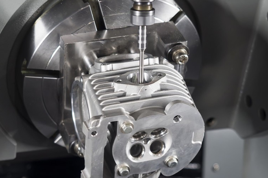
2 Wavelet analysis principle of overcut signal in free-form surface processing. In cnc machining, the intersection of the tool end face and the surface of the workpiece is called over-cutting. It belongs to abnormal cutting. When the free-form surface of the workpiece is overcut, the cutting force suddenly changes, resulting in The cutting power changes, and the motor current that drives the tool will also change accordingly. Therefore, monitoring the change of the motor current with the cutting force can indirectly monitor the tool status and extract the current signal from the spindle motor. The simplest method is to perform I/ with a series resistance. U conversion, output in the form of voltage, but the addition of resistance changes the load characteristics of the motor itself, which reduces the accuracy of the measurement. In addition, other instruments connected at both ends of the resistor must be equivalently transformed to suspend its potential, which undoubtedly increases the complexity of the measurement system. In view of this, this paper uses a magnetic balance Hall current sensor. The sensor itself is connected to a DC power supply. A magnetic field is generated inside the Hall element. When the current input terminal of the motor is connected to the sensor, current is generated at its output terminal. It generates a balanced magnetic field inside the Hall element. If the motor current changes, the balanced magnetic field will be affected. In order to achieve a new balance, the output current must be changed accordingly. Because the Hall element has a good linear relationship between input and output, the fluctuation of its output signal can indirectly reflect the change of the motor current. Set the output signal Is f(t), then the continuous wavelet transform of f(t) can be defined as the multi-resolution approximation of the inner product of f(t) and,)(, the corresponding scale function 1, so the basis function of V/space should also be located In the V/+i space, the canonical orthogonal basis of the V/+i space can therefore be used to express the approximations of 1 and 2’respectively in the orthogonal projection of V/+i and V/. According to the projection theorem, the resolution The detail signal of 2’should be the orthogonal projection of the original signal on the orthogonal complementary space of V/about V+1. Let this orthogonal complementary space be W/, that is, the basis function of W/space 2/(x -2/n) should also be located in the V/+i space, so the canonical orthogonal basis formula (5) in the V+1 space can also be used to express the signal/(t)GV+1, then the above formula shows that f( The discrete approximation Af of t) can be obtained from the higher-level discrete approximation Ad+i/pass filter. The detail signal D/f of f(t) can also be obtained from the higher-level discrete approximation Ad+i/pass another filter. The filter h(n)g(n) is defined by the inner product of the scaling function h(t) and the wavelet function ⑴. If the original signal A0f has N samples, just give the so-called a, b( t)-a wavelet basis function, when a>1 (t) the waveform stretches, when a<1 (t) the expansion and contraction of the waveform compression parameter a and the translation of the parameter b such as continuous values, called continuous wavelet transform actual In the application, it is dyadic discretization, that is, taking a=The test is to perform wave over-cutting on the TRIACATC vertical machining center, which is mainly called the dyadic wavelet transform at the overlap of the curved surface or during the turning of the tool.
For the digital signal sampled by the computer, the dyadic signal is small overcut. Tool 2 workpieces are prone to occur. In order to simplify the test process while taking into account the basic characteristics of overcutting, this article carried out the overcut simulation test as shown. The sampling frequency is 1kHz.3.1 The test conditions for the overcutting test are as follows: The diameter of the milling cutter is 8mm , The cutting depth is 1mm, the spindle speed is n=500r/min, the feed speed is v=150mm/min, the overcut depth is Hg=0.05mm, the workpiece material is A3 steel, and the tool material is high-speed steel. The measured signal is as shown in S in the over-cut signal and wavelet decomposition. It can be seen that the time-domain signal is more complicated, and there is no obvious over-cut feature. For example, when observed in the frequency domain, real-time monitoring cannot be achieved due to the lack of positioning in the time domain. the goal of. Therefore, the original measured signal is subjected to wavelet decomposition, and the transformation results are listed in the transformation results. It can be seen from the transformation results that when the overcut occurs, the reflection on the small scale (high frequency) is not obvious, but the overcut feature is obvious on the fourth scale. It shows that in actual monitoring, a threshold can be set on this scale to identify the cutting state, and its cross-cut point is accurately located in both time-frequency directions in the wavelet transform graph, which is convenient for real-time monitoring. 3.2 Cross-cut test Two test conditions: milling cutter diameter is 10mm, cutting depth = 0.5mm, spindle speed n=500r/min, feed speed v=150mm/min, overcut depth Q1mm, workpiece material is A tide, tool material is high-speed steel The measured signal and its wavelet decomposition can be seen from the figure. It can be seen from the figure that the over-cutting point is not obvious in the high frequency range. Also on the fourth scale, the over-cutting feature is clearly displayed. 4 Conclusion Wavelet transforms into the time-frequency localization of the signal Provides a mathematical foundation, adopts wavelet analysis method, can analyze the signal from the time domain and frequency domain at the same time, and carry out precise time-frequency positioning of the points of interest. In the NC machining of the free-form surface of the workpiece, overcutting is a common form of failure. The entry point contains rich frequency information, but it is difficult to obtain relevant information about the overcutting only from the time domain observation. Wavelet analysis can observe the signal at different times and segments, and can accurately extract various information about the frequency mutation point. It shows that at time, the space uses “focused” scanning to observe the overcutting information. Although the reflection is not obvious in some frequency bands, in other frequency bands, the wavelet coefficient value is obviously prominent, which can effectively identify the cutting state of the tool in real time. Tool status monitoring lays the foundation
Please keep the source and address of this article for reprinting: The Wavelet Analysis Of Overcut In Free-Form Surfaces CNC Machining
Link to this article:The Wavelet Analysis Of Overcut In Free-Form Surfaces CNC Machining
Reprint Statement: If there are no special instructions, all articles on this site are original. Please indicate the source for reprinting:Mold Wiki,Thanks!^^

